


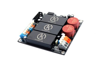
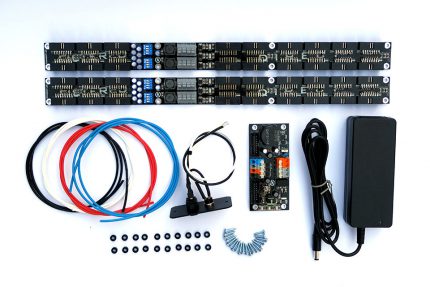
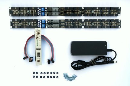
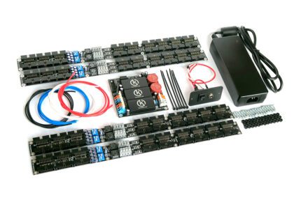
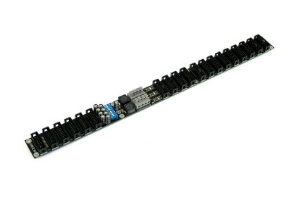
A low profile bus board with extra filtered output headers. This is an ideal bus board for all Konstant Lab power supplies but also works with other eurorack power supplies as well.
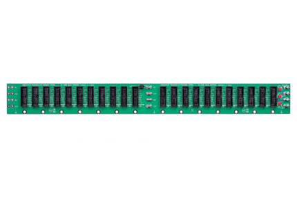
The Busboard contains 18 output headers. 12 direct headers with decoupling capacitors and 6 filtered headers with unique filtering circuits. Filtered headers are specially dedicated to feed analog modules that are sensitive/susceptible to power quality.
Decoupling capacitors and LC filters reject noise caused by PSU and digital modules by 70%. Two 4 ways DIP switches can tune filtration capacity when some PSU has starting problems with big capacity on output – especially handy if you have a lot of digital modules present in your system.
Each power rail is protected against overvoltage for your modules and systems safety. 3 blue LEDs indicate the presence of voltage and voltage drop
90% of the bus board area has only 11mm in height with inserted connectors. This feature makes Filtered bus board an ideal power distribution solution for skiff cases where depth is a concern.
Dimensions :390mm x 30.5mm x 11mm high ( 18mm at wire connection point , 14mm over filter switch area) Weight: 162g
Additional info from the manual:
Modules connection:
1. Filtered Bus Board has two areas. DIRECT and FILTERED.
2. Connect all digital modules and all noisy modules in to DIRECT area. Filtrating capacitors will keep low noise level in power network.
3. Connect all pure analog modules and modules sensitive to power quality to FILTERED area. LC low pass filter keeps separated your sensitive modules from digital and noisy modules. Do not connect digital modules in to FILTERED area, because main purpose of Filtered Bus Board is separated digital and pure analog modules.
4. Each DIP swich has two levers ON and two levers OFF (default position).
5. Switch on PSU. If PSU starts ok, all three LEDs on Filtered Bus Board should light. If +12V or -12V LED not light, try to turn off DIP switch step by step, until PSU will start correctly.
DIP Switches:
Filtered bus boards come with 2 levers ON and 2 levers OFF on the both DIP switches. It is the most universal and default setup. A DIP switch connects capacitors near switches to the filter circuits. One lever for one capacitor (in total 8 switches for 8 capacitor, 4 for +12 V and 4 for -12 V). In case there is a lot of noise produced by some module in the system, rest of the levers can be used to connect more capacitors to decrease noise.
Also sometimes can be necessary to disconnect some capacitor because there can occur high inrush current during starting sequence of PSU. Some PSU can have issues with starting because of high capacitor charging current. Switching DIP OFF can helps improve PSU behavior during the start.


Reviews
There are no reviews yet.